Hembyggd flödeskontroll till e61

basiecally

Well-known member
Hej!
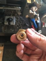
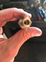
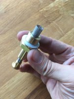
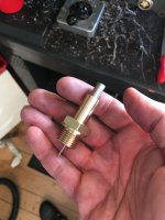
Har lyckats åstadkomma en nålventil för flödeskontroll till min Isomac mondiale. Hade ingen förlaga att jämföra med så jag fick gå på vad som känns rimligt.

Den nya ”svamptoppen” är svarvad i mässing och själva nålen är rostfritt. Valde en M6gänga för justeringen, den ger 1mm/varv och det blev rimligt med en kona på 2 grader på nålen. Har även tillverkat en gicleur med ett hål på 2mm som ska matcha. Med nålen längst urskruvad motsvarar det en öppning på strax över den 0,8mm diameter öppning som fanns där i original. Helt inskruvas stänger den av helt, om mina beräkningar stämmer.

Nästa steg blir att beställa gruppmanometer och tillverka ett trevligt handtag till den!
C47F9A23-8F49-4D83-BF96-0410D1C23F19.jpeg46EE3E3C-D87D-4A57-AFD2-C0B3BCB77D8C.jpeg5DBAB00C-FFDF-4E85-B5CE-1CF33E6520C6.jpeg862B988E-3782-46F2-A359-604017E01C2E.jpeg
 

basiecally

Well-known member
E3F40823-3B34-4ACC-850C-A5F85547FF2F.jpeg9BCF9CF9-423B-4F89-866A-EF4386D3C5AF.jpeg
Visa bilaga IMG_3891.MOV
Nu är den klar! Jag köpte några extra gicleurer som reservdelar och en gruppmanometer. Fick justera hålet i gicleuren ett par gånger innan vredet i botten verkligen betydde stopp på flödet. Tog det säkra före det osäkra och förkopprade hela grejen. Passade även på att förnickla delarna som syns men som inte har kontakt med vattnet. Handtaget är en liten bit svart delrin som jag försökte matcha med handtagen för ånga och varmvatten. Hela grejen är på tok för lång egentligen men jag hade ingen aning om vad jag höll på med när jag började. Har typ 11mm slaglängd på nålen och i realiteten behövde jag 2. Avståndet fördubblas dessutom eftersom jag behöver ha en lika lång cylinder på andra sidan för att O-ringarna ska ha en yta att glida/täta mot. Får jag för mig att bygga en ny vet jag vad jag ska göra iaf!

Den funkar verkligen nu! Såhär i efterhand kanske jag skulle ha valt en brantare gängstigning eller en brantare vinkeln på konan på nålen. Nu får jag vrida nästan ett helt varv för att variera mellan 6-9 bar med ett passande malt kaffe i 15g-korg. Det går verkligen att påverka smaken med den här, har fått skott med bra crema, om än ljus, men nästan helt utan rivet i halsen. Drar jag på till 9 bar så kommer det tillbaka. Ska testa med ljusrostat snart.

BEFB7EF2-F9B4-4739-B921-C6CF246CCC50.jpeg3C9299D2-D99C-4A07-8FE9-8193A5A5B87A.jpeg
 

Jonken

Well-known member
Moderator
Härligt! Och snyggt :) alltid roligt när någon delar med sig av mer avancerade projekt som det här.

Nästa steg i resan kanske kan bli att bygga en egen kafferost?
 

Mayhem

Well-known member
Moderator
Wow! o_O Väldigt imponerande att snickra ihop det där själv. Varje gång man ser sådana här trådar eller maker-kanaler på YouTube önskar jag att plats för en riktig verkstad, pengar att köpa en hel maskinpark, och tid att lära mig tillverka allt roligt man kommer på.

Skulle det vara möjligt att kontraktera dig att bygga en liknande del eller två till min egen espressomaskin?! Skulle framförallt vilja ha en replika av den del som tillhandahåller flödeskontrollen i espressomaskiner från Slayer. Det är ett litet block med vatten in respektive ut på varsin ände, genom blocket går två vattenvägar där den ena kan trimmas in med en nålventil och den andra blockeras eller öppnas av en solenoid. Konceptuellt en ganska enkel del men kräver hög tillverkningsprecision, vilket du redan verkar ha full koll på… 💰💰💰
 

orzel12

New member
@basiecally

Hej, bra projekt! Skulle du vara så snäll att förklara steg för steg exakt vad du gjorde eller ge ritningar? Jag skulle vilja göra något liknande min kaffebryggare eftersom jag som student inte har råd med flödeskontroll från butiken. Jag skulle vara mycket tacksam för hjälp. Om du pratar engelska kan du skriva på engelska, jag använder en svensk översättare. Hälsningar
 

basiecally

Well-known member
@basiecally

Hej, bra projekt! Skulle du vara så snäll att förklara steg för steg exakt vad du gjorde eller ge ritningar? Jag skulle vilja göra något liknande min kaffebryggare eftersom jag som student inte har råd med flödeskontroll från butiken. Jag skulle vara mycket tacksam för hjälp. Om du pratar engelska kan du skriva på engelska, jag använder en svensk översättare. Hälsningar
Hey!

I don’t have drawings and it was more or less trial and error as I went. Started with some hex bar stock for the body of the valve and turned both an outside and an inside thread, as well as a cylindrical register for the o-rings to seat against. I also tapped a hole for an original gicleur for an E61 group. The needle was made from stainless bar stock, turned to a 1 degree taper in steps. I made the tread an M6x1 that I just tapped in the brass body and cut with a die in on the needle. It’s a metric standard thread. I calculated the orifice of the gicleur, the taper of the needle and the pitch of the thread to get a meaningful increase of the area in the gicleur with each full turn of the device. In retrospect, I could have used quite a coarser thread. To go from 9 to 6 bar during brewing I usually have to do a little over a full turn.

I opted for a double o-ring seal. A single might have been sufficient, the thread provides some sealing if made properly.

The upper assembly is optional. I went for a look that matches the rest of my machine. I also electroplated the brass as I wasn’t sure if it was lead free.

Note that my described process above assumes you have access to, and know how to operate, a thread cutting machine lathe. I would suggest looking up cutaway schematics for metering valves to get an idea of how they are constructed, if you want to try your hand at making one of these.
 
Senast ändrad:

orzel12

New member
Hey!

I don’t have drawings and it was more or less trial and error as I went. Started with some hex bar stock for the body of the valve and turned both an outside and an inside thread, as well as a cylindrical register for the o-rings to seat against. I also tapped a hole for an original gicleur for an E61 group. The needle was made from stainless bar stock, turned to a 1 degree taper in steps. I made the tread an M6x1 that I just tapped in the brass body and cut with a die in on the needle. It’s a metric standard thread. I calculated the orifice of the gicleur, the taper of the needle and the pitch of the thread to get a meaningful increase of the area in the gicleur with each full turn of the device. In retrospect, I could have used quite a coarser thread. To go from 9 to 6 bar during brewing I usually have to do a little over a full turn.

I opted for a double o-ring seal. A single might have been sufficient, the thread provides some sealing if made properly.

The upper assembly is optional. I went for a look that matches the rest of my machine. I also electroplated the brass as I wasn’t sure if it was lead free.

Note that my described process above assumes you have access to, and know how to operate, a thread cutting machine lathe.
Thank you for your answer. I have access to a lathe, milling machine and other tools. I ordered my new machine with the e61 group and I'm already planning to install flow control. It will probably be easier for me to understand this mechanism when the espresso machine comes to me.

Thanks again
 

basiecally

Well-known member
I edited my response since you replied, not sure how much it adds.

If you are familiar with machining techniques, I learned a method for turning tapers on slender parts that works well. You need a repeatable collet system for it to work reliably though. You set up a flat faced, very sharp tool, preferably HSS. Then you indicate the face of the tool in to the desired angle. With very little stick out of the stock you then turn it down until you reach the minor diameter of the taper. Then you advance the stock in the collet and turn down the next section until the far (distal) end of the tool just contacts the work. This requires a tool with a wider cutting surface than the cut being made. Then you keep doing passes until you reach your major diameter. This leaves very little steps to blend and can be done with a flat stone. The main benefit it that the only time you are turning the thin sections of the taper is when they are well supported and close to the spindle nose. Often times, turning a shallow taper on a thin part in multiple, longitudinal passes results in a trumpet shaped part. The stock will flex away from the far end. Plus it is very hard to support with the tail stock. I made a few attempts before testing this technique and it all resulted in broken parts…

I agree that you will get a better idea of the construction of the mushroom of the E61 once you have it in hand. It’s just a matter of mating parts and replacing the top nut with a metering valve. The concept is really super simple but it does present some interesting machining challenges.
 

Forumstatistik

Trådar
14,840
Inlägg
156,981
Medlemmar
19,471
Senaste medlemmen
Peter L
Topp